Create Additional Rooms (Introduce new material)
We will create two additional rooms: The Executive and Secretary combination space and the ST-12 Open Office and hallway combination. In these two operations we will introduce surface removal and changing surface color and texture.
Secretary and Executive
- Select the viewpoint “Secretary and Executive” to retrieve that view.
- Click the Add Room – Polygon command.
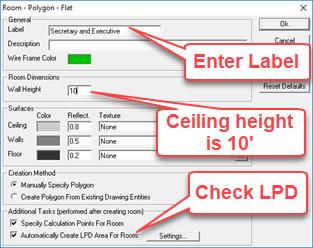
- Enter the Label “Secretary and Executive”.
- Change ceiling height to 10’.
- Make sure LPD area is checked.

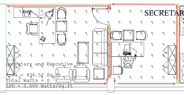
- Click OK and trace as shown below. Be sure and capture the detail of the room by tracing the outline carefully, this will be important in the next step. Do not trace across the doorway between the two spaces, make them one contiguous space. If you make a mistake as you click in the points simply press ctrl-Z to back up one step (repeat to back up further).

-
Right-click to close the polygon room (after upper left point)
-
Accept the default when the calculation points dialog appears (click OK)
You may have noticed that we created a wall across the north side of the Secretary space that should not be present. Because we have inflection points (nodes) at the edges where the void should be, we can remove that portion of the room geometry using AGi32’s Surface Edit command.
- Select the Surface Edit button from the Rooms/Objects toolkit.
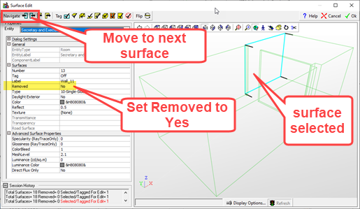
- The command will change the cursor to a selection box, click anywhere on the room perimeter then right click to accept.
- Surface Edit will open with the floor highlighted (selected). You can move the selection around to other surfaces using the blue buttons in the upper left portion of the dialog (see below). Find the desired surface.
- Change the Removed property to Yes.
- Click OK to exit Surface Edit.

We now understand how to remove surfaces from Rooms and Objects in AGi32. For future use, you can select multiple surfaces in the dialog by “tagging” them. Just press the F8 key when selected. When all surfaces are tagged, set the property.
ST-12 and Hallway
Moving on, let’s create the room for the large open space and hallway: Open Office ST-12. The viewpoint we set for this area does not encompass the hallway so we will work from the larger overall view.
- Select the viewpoint to SW corner – Level 1.
- Select the Add Room – Polygon command.
- Enter the Label: Open office ST-12 and hallway.
- Set Wall height to 10’.
- Make sure the LPD area is selected as before.
In the dialog we will make some additional changes:
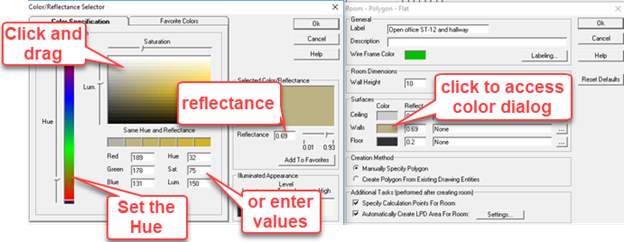
- Click in the Color cell next to Walls.
- The Color/Reflectance dialog will open (shown below).
- Move the Hue slider to the orange area, or enter Hue=32
- Place your cursor in the Luminance/Saturation area, click and move around, notice the values for Luminance and Saturation changing. You can enter the following values in the cells provided manually: Saturation=75 and Luminance=150. This equates to a reflectance value of 69% (0.69).
- Click the Add To Favorites button to store that color for future use.
- Click OK to exit the Color/Reflectance dialog with that setting. Notice we have changed to color and reflectance of all walls in the room we are about to create.
- Do not exit the main dialog!

- While you are still in the main Room – Polygon dialog, click on the button with the ellipsis (…) on the right side of the Floor row (below). This will allow us to assign a texture to the floor.

- In the Textures dialog, select Carpet on the left list of categories.
- Locate Carpet 515 in the matrix of samples, select it (notice the calculated reflectance is 30%).
- In the lower right corner select “Fixed Size” as the method of application and enter 2’ for the size. This applies the photographic sample as a 2x2 square.
- Click OK to exit the Textures dialog.
- Click OK to exit the Room dialog and begin tracing the space. It will be helpful to Zoom and Pan using the mouse as you work (wheel to zoom, hold down wheel to pan).
- Trace the space as shown below. Be sure and set node points (click) where the purple circles are. We will need these to remove surfaces.
- Right-click to close the polygon.

-
Accept the defaults for the Calculation Points dialog.
Now let’s use Surface Edit to remove a few unwanted surfaces.
- Select the room with Surface Edit.
- You can see solid geometry in the viewer by setting the “Show 3D Entities Filled” in Display Options (button at the bottom of the dialog).
- Use the Navigate buttons in the upper left corner to move the focus to the first target surface (below), press the F8 key to tag.

- Click the navigate button (go either way) to move to the next target surface, press F8.
- Keep moving to third target surface, press F8 again.
- Set the Removed property to Yes. The removed surfaces should appear as those in our capture.
- Click OK to exit the Surface Editor.
 RESCUE
Open RESCUE-Intermed_Interior-3.AGI


